May 05, 2026
The 3 gang switch wiring guide is designed primarily for electricians and DIY enthusiasts who seek to optimize electrical installations in residential and commercial settings. This guide addresses common issues such as faulty switch configurations, inappropriate load capacities, and inefficient circuit management. By understanding the wiring of three-gang switches, professionals can improve safety and functionality, thus reducing the likelihood of electrical failures. Through effective wiring, electricians can manage multiple circuits from a single switch, ultimately enhancing user experience and satisfaction.
Before diving into the wiring process, it's crucial to understand some key terminology and principles. A 3 gang switch allows control of three separate lighting circuits from one location. The basic components include terminals (often called screws), the switch mechanism, and the electrical box itself. Terminology such as "load," "feed," and "switch leg" are imperative in understanding the electrical circuit. Moreover, understanding electrical principles, such as voltage, current, and resistance, can significantly improve the efficiency of wiring installations.
You'll need the following tools: a wire stripper, a screwdriver, a multimeter, and electrical tape. The right tools streamline the wiring process, ensuring that installations are not only efficient but adhere to safety standards.
Always turn off the circuit breaker before beginning work to prevent any shock hazards. Use a multimeter to ensure that no current is flowing through the wires before proceeding.
Examine how many circuits you will be controlling with your 3 gang switch. Identify which wires are the feed wire (supply power) and which are the load wires (which will go to the lights).
Using a wire stripper, strip about 3/4 inch of insulation off the ends of the wires. This ensures optimal conductivity. Ideal wire gauge should be 14 AWG or 12 AWG, depending on your circuit load requirements.
Attach each load wire to their respective terminals on the switch. Typically, the wire that is connected to the lower terminal is considered the "common" terminal. Ensure a secure connection; a loose connection can lead to increased resistance and potential overheating.
Secure the ground wire to the green grounding screw of the switch. Grounding is crucial, as it protects both users and electrical equipment from surges and faults.
Carefully push the switch back into the electrical box, ensuring that no wires are pinched. Secure the switch with screws to the box.
After ensuring everything is properly connected, turn the power back on. Test the function of the switch to verify that each gang operates as intended. If all switches function correctly, tape up any exposed wiring for additional safety.
Q1: What type of wire should I use with a 3 gang switch?
A1: It’s recommended to use 12 or 14 gauge wire, depending on your load requirements. For example, a standard 15-amp circuit requires 14-gauge wire, while a 20-amp circuit requires 12-gauge wire.
Q2: How do I troubleshoot if the lights do not work?
A2: Check the circuit breaker, ensure the switch connections are secure, and use a multimeter to check voltage at the switch.
Q3: Can I connect multiple loads to a single gang?
A3: Yes, but ensure that the total amperage does not exceed the circuit’s rating to avoid overheating.
For seasoned electricians, consider exploring advanced wiring techniques, such as circuit interlinking, where multiple 3 gang switches can control the same light fixture from different locations. This could increase user convenience in larger spaces. You may also look into smart switches that allow for remote control via apps, drastically improving user experience.
If you're looking for quality switches and electrical accessories, consider products from Sager. Their offerings are designed to meet rigorous safety standards and can enhance the overall reliability of your electrical installations. For further assistance or detailed product inquiries, do not hesitate to contact Sager directly.
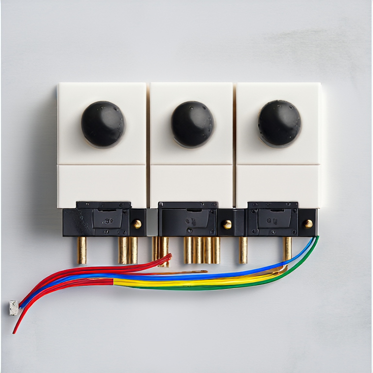
For more detailed diagrams and illustrations about the wiring process, check the reference image provided: